Once you have a subsystem created, there is the possibility of mask it.
Mask a subsystem could be useful in order to customized the block and make it more accessible to an external user.
Let's take a past example to modify it and demonstrate the mask application. First of all, we take the past post '
Create a Subsystem'. If we remeber this post, I created a simple subsystem of an LR Load.
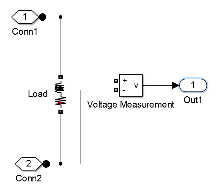 |
| Circuit inside subsystem |
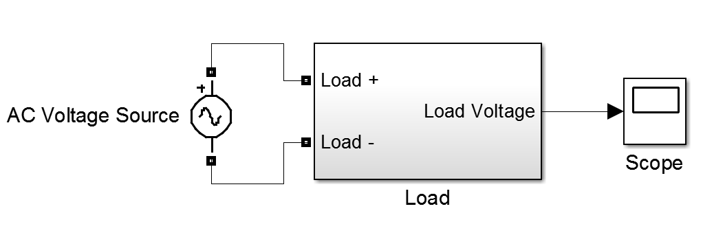 |
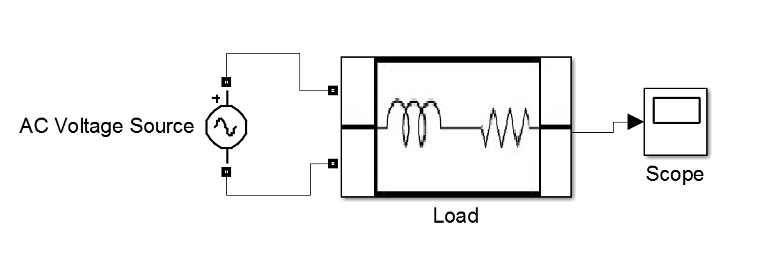
| Load Subsystem |
Now, let's mask the subsystem, customizing the previous image, and also adding some external parameters. The external parameters are useful to change the parameters on the circuit without getting inside it.
If we want to mask the subsystem, right-cliking the block, and selecting mask/create mask... or Ctrl + M when the block is selected. Then, the mask editor should open:
The mask editor allow us to change some of the subsytem options. For example, we can change the previous image of the subsystem in the first tab:
Icon & Ports. Here, we can draw with Matlab plots, we can upload an image, etc.
In our case, let's take a simple image that represents our load:
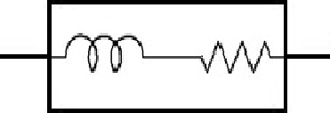 |
| RL Load |
In order to upload to the subsystem, the image should be in a Matlab path or a known path. In our case, the image is inside the current directory.
Now, we program the command:
image (imread ('Load2','png'));
When we click apply, the changes can be seen:
 |
| Subsystem with image customized |
Now, we are going to add some external parameters. Let's go to the
Parameters pane:
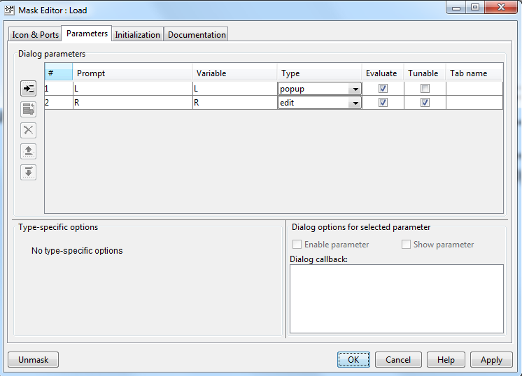 |
| Parameters tab |

Button to add a parameter.
There are different kind of parameter types: edit, checkbox, popup, DataTypeStr, Minimum and Maximum. In this example we are going to use edit and popup.
In the case of the popup parameter, there is a list of options that we can choose. In the case of edit, any number could be added to the subsystem.
In our case, let's limit the L values options to 330H and 390H.
Notice that in 'Type-specific options' we have specified the options we want.
Now, after clicking apply, the subsystem would appear like the following:
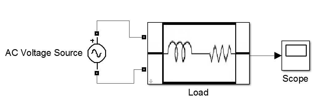 |
| Subsystem with mask |
Now, in order to descend to the circuit, we have to click the arrow:

When we normally click to the block, the window below will appear:
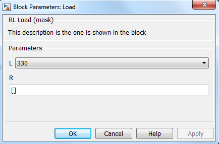 |
| Subsystem window |
Notice that the R parameter has to be entered, and we can choose L value between 330 and 390 H.
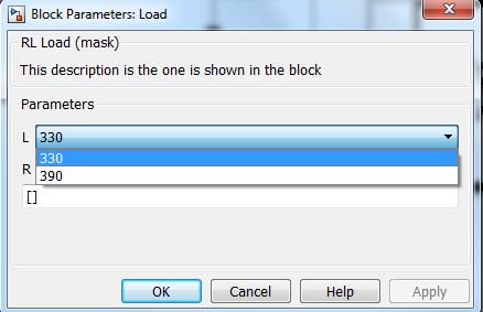 |
| Subsystem window with popup |
In order to make these parameters applicable in the circuit, we have to change the real values of R and L to our variables: 'L' and 'R':
Now, if an external user has to use the block, there is a mask to facilitate the options, like the different blocks in Simulink.
There is an
initialization pane to initialize the mask block. Here we can add Matlab code that we like to run before the simulation starts.
Finally, lets add some information to the external users that can help them to understand our block. We can see a
Documentation tab, where there are three sections: Mask type, Mask description, and Mask help.
Here, a explanation of the block must be added, in order to make it more understandable. The Mask type and Mask description will appear in the main window when we click the block. In we need more information, we could click the help button and the Mask help will appear:
Now, you can try with another type of parameters and options to make a more complicated subsystem. And comment the results here on the post! I will be glad to receive feedback and opinions!