Today, I would like to talk about Power Factor Measurement on Simulink.
When I had to face this problem I found a really interesting block on internet:
After some tests, I found the block ideal to measure power factor correction to displaced waves (not to distorted waves)
I did some modifications to it, but basicaly it works the same way as before. Now, I would like to explain the block:
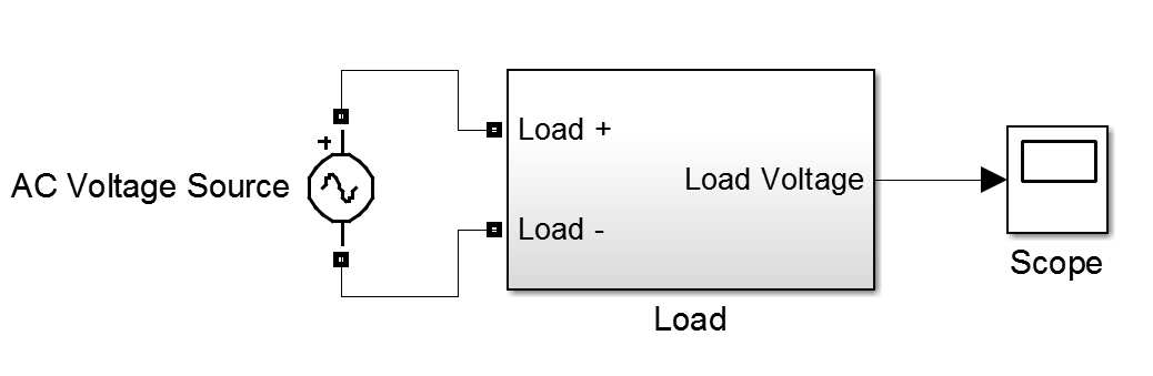
 |
| Power Factor Measurement Block |
Inside the block there are the following elements:
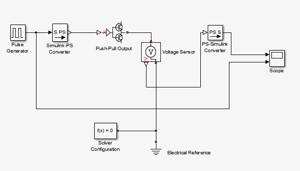
 |
| Inside Power Factor Measurement Block |
The functionality of this block is the following:
The integrator block calculates an integration of '1' until voltage or current go to zero, then the value of the integration starts again (value of each signal). This is calculating the voltage phase offset and the current phase offset in each moment t.

 |
| Voltage phase offset and Current phase offset |
The last period of the simulation will be the one the block considers. Now the constant of the phase of each signal is known, it is compared and multiplied by 2*pi*f to have the actual phase difference of the signals.
Since

The power factor is measured after cos block is applied to the actual phase difference calculated before.
After all that blocks the power factor for displaced waves is measured.
Finally, I would like to show an example:
If the output of the example is plotted the dispersion can be seen:
Finally, I would like to show an example:
 |
| Example: PF Measurement of displaced signals |
 |
| Example: V vs I (displaced waves)** |
 |
| Theoretical PF Measurement of displaced signals |
It can be seen that both results match.
References:
Saurabh Kabdal
Gautam Buddha Technical University (GBTU), U.P, India
Notes:
**Notice that current wave has been multiplied in order to be compared with voltage in the plotNotes: